Precision Mold Design & Manufacturing

Progressive Die for a U-Bracket, 120 mm Pitch, 3 Bends

Model: N/A

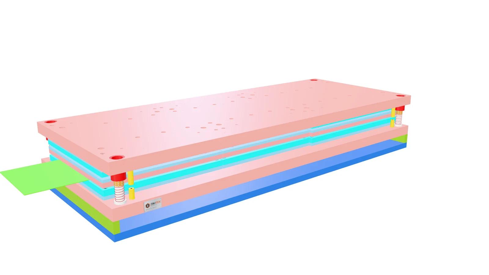
3D model of Progressive Die for a U-Bracket, 120 mm Pitch, 3 Bends

Tính năng nổi bật

Progressive die for a 2 mm sheet-steel U-bracket: 310 mm strip, 120 mm pitch, piercing – blanking – three bends on both sides – cut-off to a chute. Turn the moving 3D model and switch on the architecture view right on the page.

  • 2 mm sheet steel, 310 mm strip, 120 mm feed: piercing, outline blanking, both side walls bent in 3 bends, then cut-off; the part slides out on an inclined chute at the end of the die.
  • Walls and tabs bend progressively with the punch on the down-stroke and reach 90° exactly at bottom dead centre; the 3D model shows every bend, the slugs dropping through the relief holes and the part sliding down the chute.
  • Architecture view: the frame plates (shoes, backing plates, punch holder, stripper) turn see-through with box outlines while punches, die inserts, pillars, lifters and springs stay solid, so the inside of the die is easy to read.
  • Stripper suspended on 12 Ø16 shoulder bolts (10 mm hanging travel) and supported by 8 hosed nitrogen gas springs in the lower die (Micro-size, ~170 daN, Ø12 rod, common charge through port tubes passing the die shoe – identified from the geometry, part numbers not verified); the rods follow the stripper as the die opens.
  • 28 spring-loaded Ø16 lifters raise the strip 44.5 mm (their full travel, 1.5 mm to spare) so the brackets clear the forming blocks; the feeder only pushes around top dead centre, once the upper die is open at least 70 mm and every pilot is out of the strip.
  • Guided by 4 ball-cage pillar sets kept at the original drawing sizes; punches, dies and forming blocks in SKD11 hardened to 58–62 HRC, frame plates in S50C; screws, dowels, pillars and bushes are standard parts.